- Reverse Correction
- Category:Reverse Correction
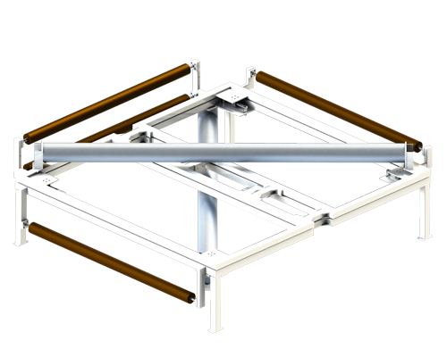
- Abstract:The roll frame is used to turn the material 90°and 180° and to adjust the position of the material at the same time. The installation position of the overturning roller stand is 45° from the direction of feeding and discharging. The material is turned180° around the roll frame and is at right angle to the feed direction when it leaves the roll frame.
Detailed Description
-
Turnover correction device
Function
The flip frame system is based on a simple principle:a round wheel is installed at 45° with the longitudinal axis and the transverse axis, and the contact radian with the material is 180°,which can immediately change the material direction of 90°.In order to guide the material at the same time,the roll wheel is installed on the plane parallel to the feeding surface.According to the signal generated,when the material is turning.Adjust material position.
Application
When using the overturning frame,there must always be a point-by-point force transfer between the overturning frame and the breadth.In order to protect the material surface,an air cushion can be used between the overturning frame and the breadth to reduce friction.In this way,the highest adjustment accuracy of (+1 mm) can be achieved.In order to improve the dynamic characteristics of regulation,besides the overturning frame,the collar should also be operated with the guide roll.The distance between the guide roll and the fixed roll should be half of the width of the breadth.Sensors must be installed directly behind the discharging roll as far as possible.


180 degree reverse correction 90 degree reverse correction
Legend illustration
A-AStress distribution of material width at feed end 1 Rotating point
B-BStress distribution of material width at discharge end 2 Feed end roller
K Material width correction quantity 3 Frame
α Maximum deviation correction range ±5° 4 Electro-eyes
σ1 Basic stress of material width 5 Fixed roller
σ2 The resulting stress distribution as swinging Lu Transmission length
rectifying roller at feeding end L1 Feed length
σ3 The resulting stress distribution as swinging L2 Discharge length
rectifying roller at discharge end AB Working width


